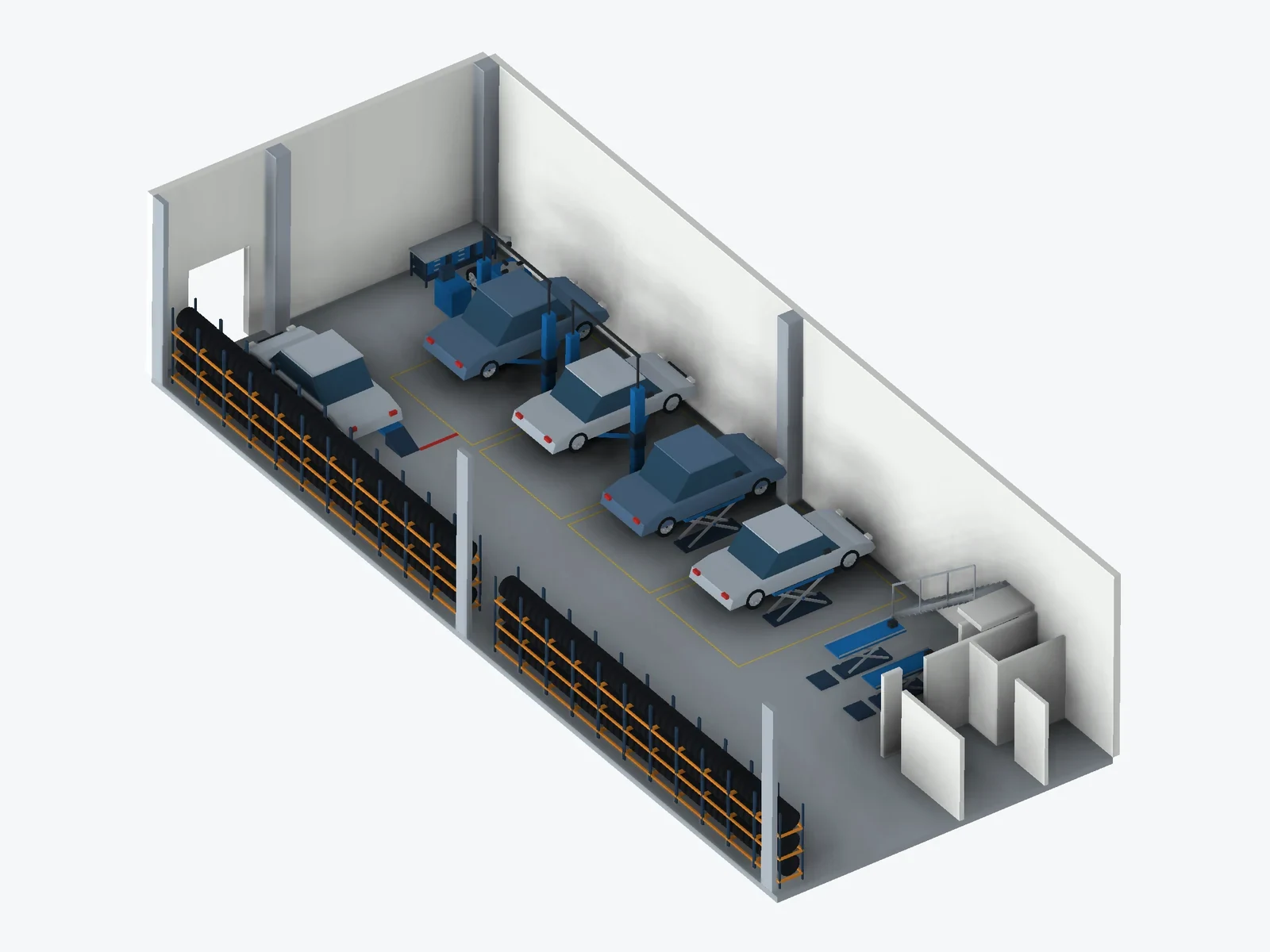
Workshop · revisions R1–R3
Mechanical workshop
From an initial proposal to phased installation. Three Inventor assemblies show how work bays change as the client revises priorities, equipment and installation sequence.
From R1 to R3
Client feedback becomes traceable revisions of the model and layout, with AI assistance and designer review.
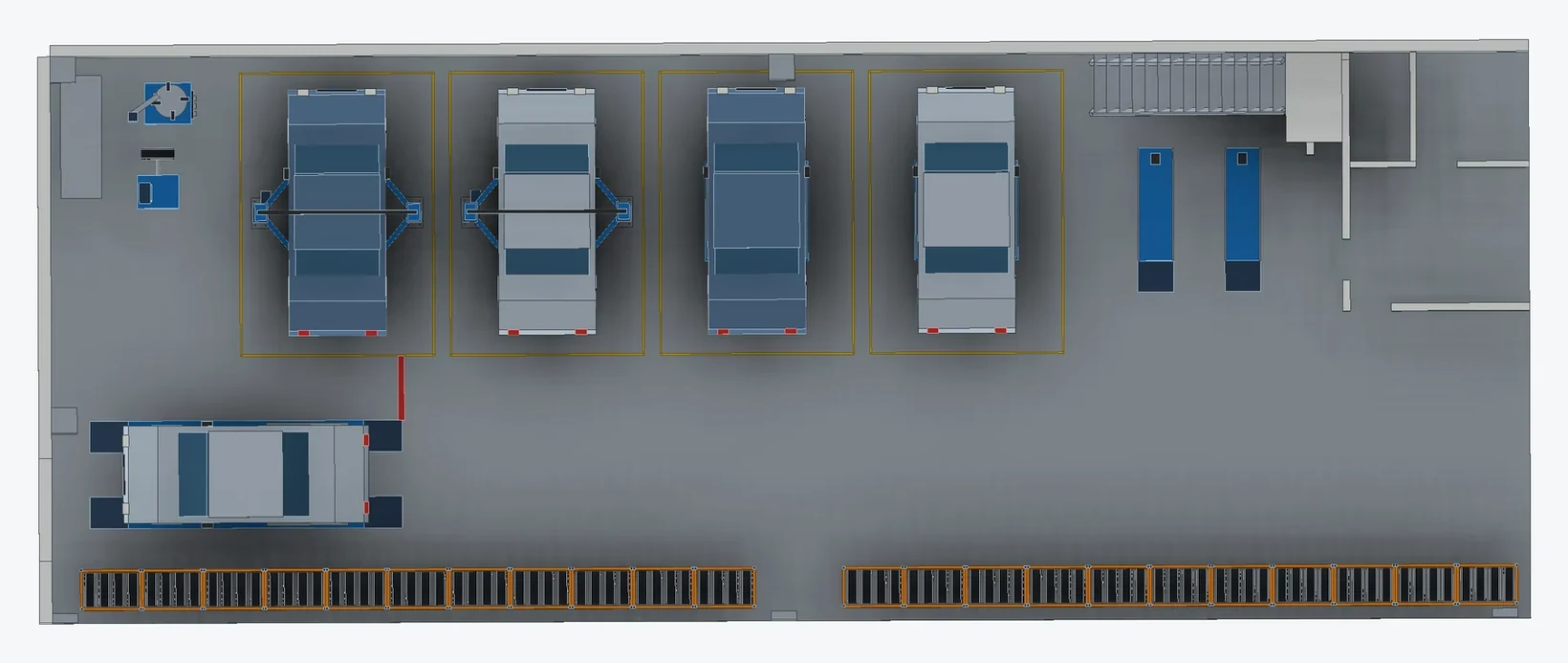
R1 · Initial proposal
Both motorcycle lifts occupy the front area. The rear C2 bay is assigned to cars. The A1 wheel-alignment bay sits on the opposite side.
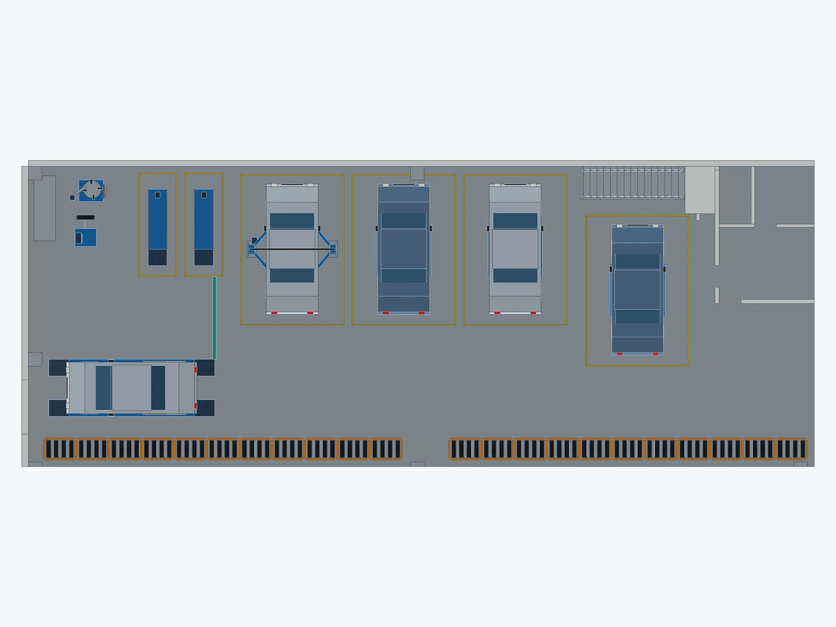
R2 · Motorcycles to the rear, F3 at the front
M1 and M2 move into the former C2 bay. Their old front area becomes F3 for air-conditioning service and diagnostics, offset towards the centre to give the stair more room. The study distance from the alignment lift to the new motorcycle bay boundary changes from 1,250 to 3,050 mm.
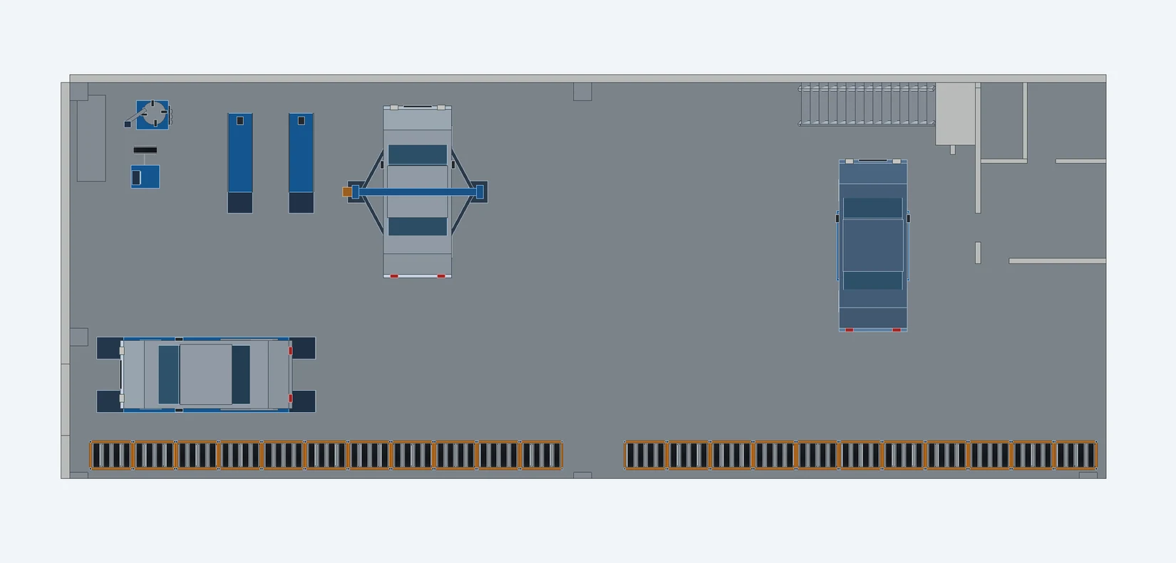
R3 · Two-post lift and phased installation
Phase one keeps F3, C1 and A1. C1 receives a new two-post lift in the existing bay. Comparing its 3,920 mm base width with the 3,800 mm bay makes the site check clear. The tyre shop and rear equipment follow the V2 arrangement.
Study dimensions. Installation, operating clearances and safety distances require site verification.
Explore the 3D model
Orbit the model and zoom into details. Open it in a separate tab for a larger view.